In this research the blower is designed air 1 Radial perpendicular to inlet flow direction horsepower is 7 ahp 52 kW and the brake 2. Lobes or impellers rotate in four positions during operation.
Applied Sciences Free Full Text Vibroacoustic Optimization Study For The Volute Casing Of A Centrifugal Fan Html
And a separate blower system with 5 HP motor fitted at one end of the plant.

. Vortron understands this concept better than anyone. Given the high performance of the baseline impeller the. Centrifugal fans or blowers are most reliable and can be used in vivid environments and for numerous applications.
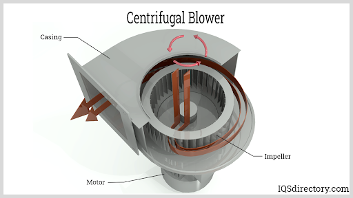
The centrifugal blower consists of two main parts. The simple design and structure of centrifugal blowers is the main reason for their popularity as well as their high endurance and reliability. Abstract- Impeller design plays an important role in manufacturing centrifugal blowers because without proper design the blowers cannot function effectively.
A volute is a spiral-like geometry with an incr. Not be in surge. The belt drive design has been made as compact as possible.
The double-discharge volute casing is a structural constraint and is maintained for its shape. Step by Step designing the Spiral Casing of a Centrifugal PumpA pump casing is often referred to as a volute. Of air at 60 F and design speed 3450 rpm.
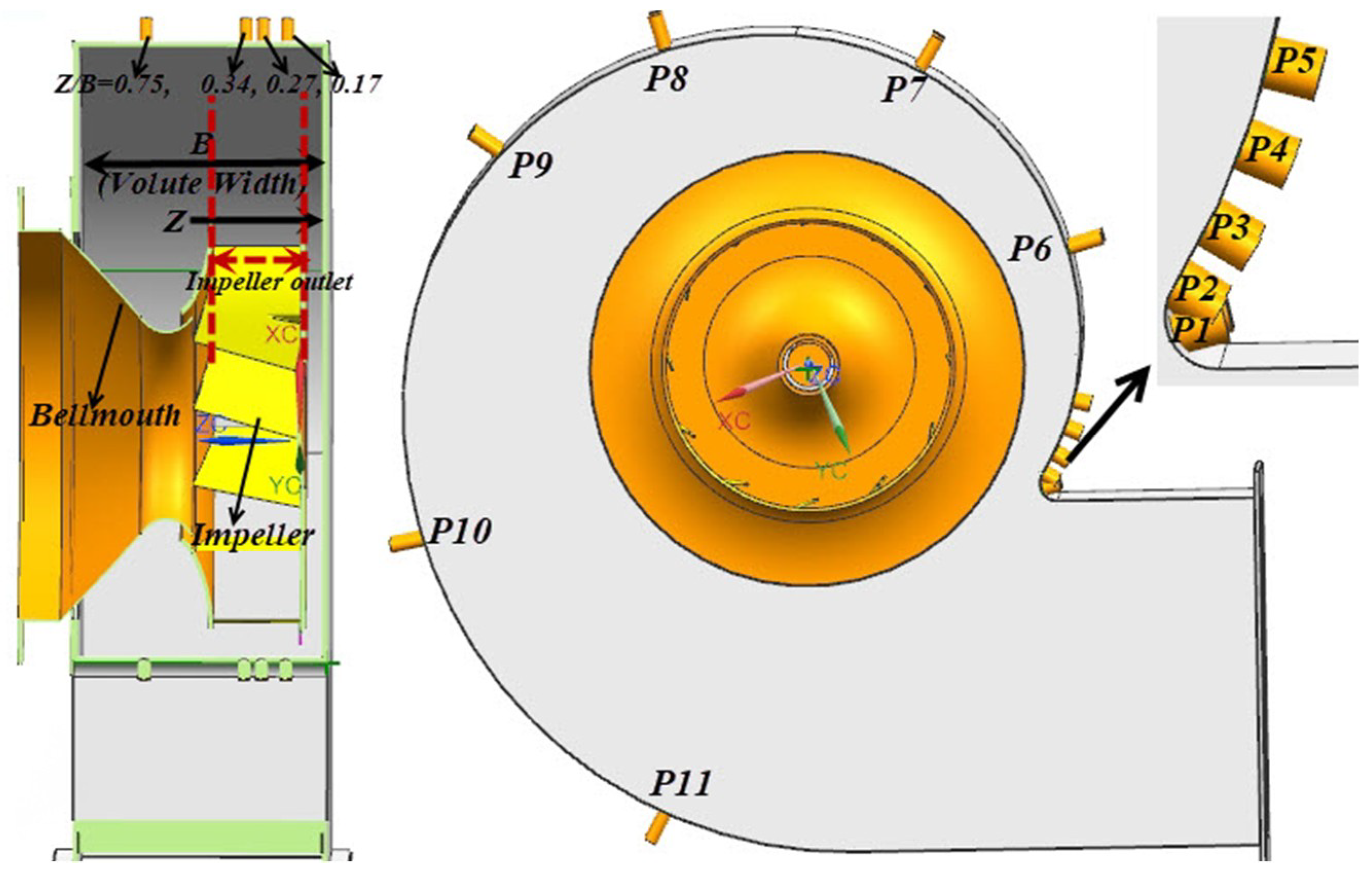
A CAD model of centrifugal blower assembly is designed in CATIA software. The design of centrifugal blowers includes a motor fan wheel and a housing. Classical fan and blower basic spiral casing design is based on a free vortex flow pattern and the assumption of a circumferentially uniform flow at the operating point where the flow rate through.
An impeller and the casing. A centrifugal fan is a mechanical device for moving air or other gases in a direction at an angle to the incoming fluid. As the shafts continue to rotate this pocket.
Gasifier using locally available materials. When the impellers rotate the gas near the impellers is thrown-off from the impellers due to the centrifugal force and then moves into the fan casing. A method is presented for redesigning a centrifugal impeller and its inlet duct.
The detailed design procedure for volute type pump casing is carried out. If you compare air knife systems from. Machine constitute a third category.
In this thesis the bower volute casing is designed to provide low volume high pressure air for cooling ventilating and exhaust system that handle dust materials or. This pipe line connection is used to transport the waste from the machine to centralized blower. Research the blower is designed air horsepower is 7 a.
D 1m in d 2 d s. As each impeller passes the inlet a measured quantity of air is trapped between the impeller and the casing. Classical fan and blower basic spiral casing design is based on a free vortex flow pattern and the assumption of a circumferentially uniform flow at the operating point where the flow rate through the impeller is equal to the flow rate through the spiral casing eg.
In this illustration the top lobe rotates clockwise and the bottom lobe rotates counterclockwise Image 1. In this paper various kinds of pumps and operational sequences are described. The geometric parameters were determined to be.
As a result the gas pressure in the fan casing is increased. After choosing the design data from catalogue the results of impeller inlet and outlet dimensions and vane angle could be obtained. The redesign effort was geared towards meeting the design volute exit pressure while reducing the power required to operate the fan.
Hp 52 kW and the brake horsepower is 10 b. The key to a high-efficiency air knife system is a high-efficiency centrifugal blower. Radial type centrifugal blower volute casing design for used in required industrial area.
Single or double inlet centrifugal fan Casing made of thick welded reinforced steel plate. This paper relates to the design of casing of single-suction centrifugal pump that can develop a head of 30m. Centrifugal blowers fans Design power Vane I.
Spiral casings for centrifugal fans and blowers are widely used in industry. Design of 5 kW Radial Type Centrifugal Blower Casing. The centrifugal fans are equipped with scroll housing that helps in accelerating the air and helps in changing the direction almost to the right angle before leaving the housing of the same.
Finally the rendering of centrifugal blower is carried. This paper presents design of the -blade backward12 -curved impeller to be used in the centrifugal blower for 40 kW wood chips gasifier. Centrifugal blowers shall be of the multi-stage type designed for continuous operation 24 hours per day.
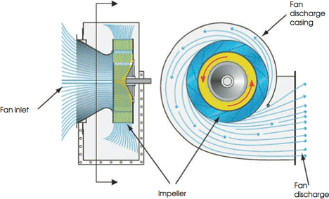
The air enters axially from center of the impeller eyes and leaves the blower radially. A blower was designed and constructed for use in the operation of a downdr aft. We have chosen CATIA V5 R20 software to design the model because of its user-friendly GUI Graphical User Interface and various commands tools which make the designing process comfortable.
The impeller is the moving part while the casing is the stationary part. This centrifugal blower can produce 20 in of wg 07396 psi and 2l2l ft3min 60 The flow direction of the liquid at the outlet of the m3min. When the fan rotates creates low pressure zone at the inlet thus intakes.
Single-Stage Centrifugal Blowers Vortron Industrial specializes in the design and manufacture of high-performance high-efficiency centrifugal blowers for air knife systems and other applications. Stainless steel centrifugal fan with flexible. When volumetric capacity is reduced by at least 30 percent blowers under indicated inlet conditions shall.
And then application and characteristics of centrifugal pump are also expressed. As a result the gas pressure in the fan casing is increased. Centrifugal blowers are the most popular type of air movement tool used for industrial and commercial applications.
Axial and centrifugal fans axial impellers roof fans smoke. Centrifugal blower has three important parts namely fan volute casing and inlet duct. Develop at least 05 psi pressure above indicated discharge pressure 2.
Design is mainly focused for the single-stage. The centrifugal fan uses the centrifugal power generated from the rotation of impellers to increase the pressure of airgases.

Schematic Diagram Of The Test Centrifugal Blower Download Scientific Diagram

Pdf Parametric Study Of Volutes For Optimal Centrifugal Fan Impellers Semantic Scholar
2
Centrifugal Fan An Overview Sciencedirect Topics
Centrifugal Blowers What Is It How Does It Work Types

Pdf Design Of 5 Kw Radial Type Centrifugal Blower Casing Semantic Scholar
Module 35 Fans For Ducted Ventilation Systems Cibse Journal

Pdf Design Of 5 Kw Radial Type Centrifugal Blower Casing Semantic Scholar
0 comments
Post a Comment